

A pin that fits the bore can still leave you with a joint that will not close properly. Check where the retainer sits, how it engages and whether it remains clear throughout the linkage travel.

Choose clevis pins and clips as a matched retaining system. Start with the pin diameter and assembled axial stack, then match the cross-hole, groove or dedicated clip interface. Confirm the retainer's seated position, axial retention requirement and removal access. A shared nominal pin diameter does not establish interchangeability.
Clevis pin vs cotter pin: what does each part do?
A clevis pin passes through the two fork legs and the mating eye to form a pivot. A cotter pin, clip or retaining ring keeps that main pin from withdrawing axially. In a clevis pin with cotter pin arrangement, these are separate components with separate jobs.
For a transverse-loaded linkage, the pin and surrounding joint need checks for shear, bearing pressure and, where applicable, bending. The retainer needs a separate axial retention check. It can experience axial force; it is not a substitute for the main pin or proof that the complete joint has a particular working load.
This distinction matters when reading a clip catalogue. A figure labelled “axial thrust” concerns retention in the stated direction and arrangement. It does not give the permissible transverse load, fatigue life or safe working load of the clevis assembly. For the wider joint geometry, see our pneumatic cylinder rod clevis and pin selection guide.
Clevis pin types and their retaining methods
Classify the connection by its retaining interface before choosing a part called a “clevis clip.” A drilled hole, a shaft groove and a dedicated spring-clip arrangement require different mating geometry and installation access.
| Pin interface | Retainer family | What the drawing must establish |
|---|---|---|
| Cross-hole near the end | Bend-to-secure split cotter pin, or a suitable spring-wire retainer | Hole diameter and position, retainer dimensions, installed leg or loop clearance, and the intended securing method |
| Circumferential groove | External circlip or retaining washer matched to its groove | Groove diameter, width and position; retainer thickness; adjacent supporting face; installation path |
| Dedicated clip and pin arrangement | Specified spring clip or folding spring bolt assembly | Exact mating designation, engaged position, closure path and removal access |
A clevis pin with wire retainer is not automatically equivalent to a pin with a split cotter. A spring-wire hairpin is designed to retain through its spring geometry; a conventional split cotter is secured by forming its legs. Do not apply one installation method to the other because both are sometimes called cotter pins.
The standard reference also needs to match the part. DIN 471:2026-05 identifies retaining rings for shafts, while DIN 6799:2026-05 identifies retaining washers for shafts. DIN EN ISO 1234 concerns split pins. These references identify different component families; none makes a generic pin compatible with every retainer of the same nominal size.
Clevis pin sizing: diameter, usable length and groove position
Check the retention position after assembling the complete axial stack. The question is not simply whether the pin passes through the holes. The groove or cross-hole must remain in the correct position once the fork, eye and specified washers are all present.
Separate radial fit from axial fit
Pin diameter and bore dimensions control the radial interface. The thicknesses of the two fork legs, mating eye and washers determine the axial stack. Overall pin length may include a head, an exposed tip or other features that do not increase the space available between the head and retainer.
For that simplified, unloaded stack, the available axial space can be written as:
C = Lr − (t1 + te + t2 + Σtw)
Here, Lr is the distance from the head bearing face to the inboard contact face of the seated retainer; t1 and t2 are fork-leg thicknesses, te is eye thickness and Σtw is the total washer thickness. This is a geometry check, not a prescribed clearance. A negative result indicates overlap in this model; a positive result still needs an acceptable limit, tolerance review and allowance for the actual retainer's geometry or deflection.
Evaluate the limiting combinations, not just nominal dimensions: the longest permitted stack must still allow correct retention, and the shortest permitted stack must not leave unacceptable axial movement. A spring clip that applies preload cannot be assessed as though it were a rigid flat stop.
Do not use a washer to hide an undefined fit
A washer changes the stack and can cover part of a groove or cross-hole. It may also change the face bearing against a retaining ring. The official DIN 988 overview distinguishes shim rings used for axial positioning and play compensation from supporting rings used where substantial axial force and chamfered faces can cause a retainer to turn inside out. A random washer is not automatically an equivalent support.
For cotter pin dimensions, compare the supplier's defined nominal size and length with the hole and installed leg envelope. If you are measuring an existing split cotter, record its unformed geometry as well as its designation; do not treat the bent leg's visible length as a universal ordering length. The installation requirement should come from the selected part and assembly drawing, not a generic bend-angle rule.
What I check before changing the clip
When I review a clevis pin and clip arrangement, my first question is where the retainer actually sits after the complete joint is assembled. A pin may pass through the fork and mating eye while leaving its retaining feature partly hidden behind a fork leg or washer. Choosing a different clip before checking that position can leave the original problem unresolved.
I would start with a section through the assembled connection. I want to see the pin diameter, the thickness of both fork legs, the mating eye, any washers and the location of the cross-hole or groove. For a grooved arrangement, I would then compare the retainer thickness and groove dimensions with the selected component drawing. Matching the nominal pin diameter is only the beginning.
Service access matters as well. A retainer needs room to reach its intended seated or closed position, and a technician needs room to remove it by the specified method. I would check nearby guards, cables and the moving linkage throughout its travel. An exposed wire loop that is convenient to grip also deserves a check for possible contact with surrounding parts.
At Dongzhou, we recommend specifying the pin and its retaining arrangement together. Our PM-K and PM-S clips, PM-E circlips, PM-F retaining washers and CL folding spring bolts represent different choices; their names alone do not establish interchangeability.
If the assembled joint rattles, my next step would be to locate the movement before changing the retainer. I would distinguish clearance in the pin-and-eye fit from axial movement at the retaining feature. That gives the drawing review a specific problem to resolve: an interface dimension, a seating condition or an unsuitable retention arrangement. The useful result is a defined assembly requirement that purchasing and inspection can both follow.
Dongzhou retention options: a catalogue comparison
These product families give buyers several ways to specify the connection. The useful comparison is their mating interface and service operation, rather than a claim that one type is always more secure.

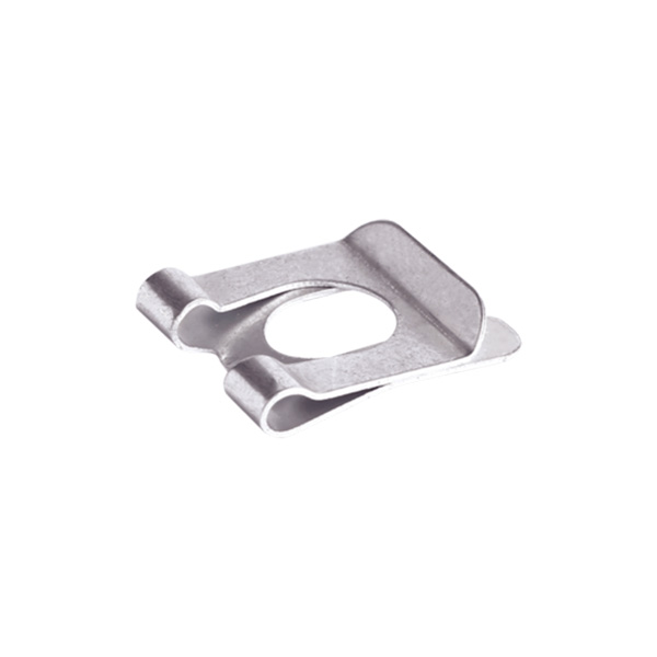


For PM-K and PM-S, “tool-free” describes the stated assembly method. It does not establish a vibration qualification or permission to replace another clip without checking the interface. Similarly, a retaining washer and an external circlip should not share an unspecified “groove for clip” note on a production drawing.
The PM-K table, for example, lists 4,850 N for PM-K6 under “Max. axial thrust ca. N.” Preserve the approximate, axial meaning of that entry. It is not a published safe working load for an FK clevis assembly, nor evidence that the joint meets a particular shock or fatigue requirement.
Why two 6 mm folding spring bolts are different selections
| CL part | Listed clevis | d | l1 ≈ | l2 ≈ |
|---|---|---|---|---|
| CL6X12 | FK6X12 | 6 | 28 | 23 |
| CL6X24 | FK6X24 | 6 | 40 | 35 |
Source: Dongzhou Folding Spring Bolts. Symbols l1 and l2 retain the catalogue's approximate dimension convention.

Both rows have a 6 mm nominal diameter, but the listed clevis changes, and both l1 and l2 differ by 12 mm. That is a catalogue geometry difference, not spare length that can be ignored. My recommendation is to send the full FK and CL designations together. An enquiry that says only “6 mm clevis pin” leaves the axial fit unresolved.
Material selection also needs to refer to the individual component. The CL page identifies a Q235A bolt and a spring-steel spring. The PM-E and PM-F pages offer spring-steel and 304 stainless options. Do not turn a stainless retainer selection into an assumption that the pin, clevis and complete assembly are all stainless steel.
How to secure a clevis pin with a cotter pin, clip or circlip
Use the following sequence to check the specified retaining arrangement. Work with the mechanism isolated, stored energy controlled and the linkage safely supported. Confirm travel clearance by the machine's approved inspection procedure, not by reaching into a powered joint.
-
Identify the specified pin and retainer
Compare the part designations with the assembly drawing. Establish whether the connection uses a cross-hole, a groove or a dedicated clip arrangement. Check the specified material and finish as well as nominal size.
-
Assemble the full axial stack
Fit the fork, mating eye and specified washers in their drawing order. Confirm that the retaining location is accessible and correctly positioned. Do not omit a washer, add an unlisted shim or force the stack together to expose a hidden feature.
-
Secure the retainer by its own method
For a split cotter, insert and form the legs as specified. For a spring-wire retainer, engage its intended spring geometry. For a circlip or retaining washer, use the specified installation method and verify engagement in the correct groove. For a dedicated folding or formed clip, confirm its designed engaged position.
-
Inspect seating, condition and clearance
Check that the retainer is not partly sitting on a shoulder, trapped behind a washer or permanently distorted. Compare axial movement with the drawing requirement. Check the installed protrusions and the required removal path against surrounding guards, cables and moving parts.
-
Record the accepted arrangement
Confirm the final pin, retainer and washer designations on the assembly record. Record the applicable seating and clearance checks, then follow the machine's approved return-to-service procedure. A visual or light manual seating check is not a load test.
“Fully seated” does not mean every retainer looks like a closed circle. An E-shaped retaining washer remains open by design. The acceptance criterion is correct engagement with its specified groove and contact geometry, not an invented requirement to close the opening.
Why does the retaining clip come loose or rattle?
First locate the movement. Radial movement between pin and bore is different from axial movement between a head, washer and retainer. A stiffer clip cannot be assumed to correct the wrong bore fit, and an extra washer can create a new seating problem.
| Observed condition | Possible cause | Next check |
|---|---|---|
| Clip will not reach its intended position | Retaining feature partly covered; wrong axial stack or part length | Compare the assembled section and washer thicknesses with the groove or hole location |
| Circlip or washer sits unevenly | Incomplete seating, debris, damaged groove or mismatched components | Inspect groove condition and actual ring/groove dimensions; do not accept a partly engaged retainer |
| Pin moves axially and rattles | Excess stack clearance or an incorrectly engaged preload-type clip | Locate the moving interface and check its specified axial movement or engagement requirement |
| Clip is bent or has lost its intended shape | Installation damage, forced fit or contact with surrounding hardware | Check component condition and assembly access before replacing it with the specified part |
| Retainer contacts a guard, cable or bracket | Closure or operating envelope was not included in the layout | Review the complete travel and service envelope; assess a different specified arrangement rather than trimming the retainer |
My preference is to turn the symptom into a drawing question: where is the unwanted movement, which surfaces should locate the pin, and what confirms the retainer is engaged? That produces a repeatable inspection. Simply asking for a “stronger clevis clip” does not.
Specify the complete pin-and-clip assembly
For a replacement or new linkage, send enough information to identify both the working joint and its retention. A photograph helps show the installed arrangement; a dimensioned section establishes the fit.
- Complete designations: clevis, pin, retainer and any washers, including the required assembly version.
- Mating geometry: bore, pin diameter, fork and eye thicknesses, retaining feature dimensions and position.
- Material and finish: identify requirements for each component, including any corrosion exposure.
- Operating requirement: transverse and axial loads, load direction changes, surrounding motion and acceptable movement.
- Service method: removal frequency, available hand or tool access and any requirement to retain loose parts during maintenance.
Dongzhou's clevis joint and clevis pin page lists an assembled folding-spring arrangement such as FK6×12-ASSY/01. The clevis joint with clip page shows FK6×12-ASSY/03 and FT6×12-ASSY/03. These full assembly codes communicate more than pin diameter alone. Specify the intended version rather than treating the suffixes as optional.
Let us review the clevis, pin and retainer together
Send Dongzhou the complete part code or an assembled section, including the retaining detail and service clearance. For custom clevis pins or a non-standard connection, include the mating dimensions and operating conditions so we can discuss a catalogue arrangement or a drawing-based requirement.
Discuss your pin-and-clip assemblyQuestions about clevis pin retention
Can I replace a cotter pin with a circlip?
Not as a direct name-for-name substitution. A split cotter normally uses a cross-hole; an external circlip requires its specified groove and supporting geometry. Changing the retaining method requires review of the pin, retainer, axial stack and installation access.
Is a hairpin cotter the same as a split cotter pin?
No. A hairpin-type retainer relies on its designed spring shape, while a conventional split cotter is secured by forming its legs. Match the actual drawing and securing method rather than assuming that the word cotter establishes interchangeability.
Does cotter key always mean the same part as cotter pin?
Terminology varies between catalogues and markets. For purchasing, use the component drawing, dimensions and applicable standard or part number. Do not approve a replacement from the term cotter key alone.
Can I reuse a clevis pin retaining clip?
Follow the selected retainer's reuse instructions and the machine's maintenance requirements. A tool-free removal feature does not by itself prove that unlimited reuse is acceptable. Replace a retainer that is damaged or no longer maintains its specified shape and engagement.