

A blank can be cut exactly to plan and still leave the mounting holes or joint center in the wrong place after forming. The drawing has to control the bracket the machine receives, not merely the sheet before the die closes.
Dongzhou lists customized stamping parts and describes a sequence from demand review and die design through tool trials, batch production and inspection. That sequence matters because a design drawing is not the same thing as a proven formed part. The buyer should set the functional targets; the factory should review whether the selected material, die plan and inspection method can achieve them. This article concerns that handoff.
Dongzhou's BRK/BDK table shows why the part number matters
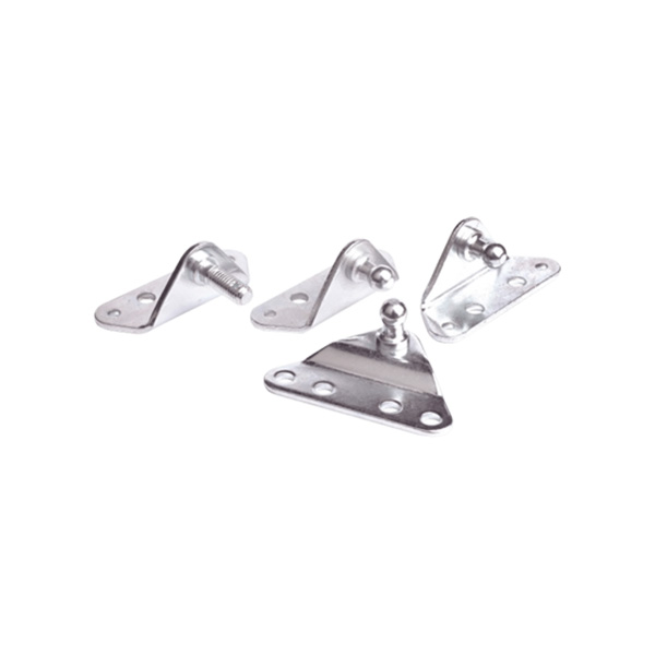
The published BRK/BDK table lists several variants, not one interchangeable bracket. BRK5558 and BRK4263 share many table entries but differ in the columns marked A, B and O. The values below are reproduced exactly as printed; the web table does not state units or explain every lettered feature in text. Use the associated drawing to identify what each letter means before assigning a tolerance or treating it as a mounting dimension.
| Published model | A | B | O | Engineering consequence |
|---|---|---|---|---|
| BRK5558 | 19.2 | 29 | 6.6 | These entries cannot be inferred from the product photo. |
| BRK4263 | 20 | 30 | 4.3 | The buyer must select the exact variant and confirm the lettered dimensions against its drawing. |
Source: Dongzhou BRK/BDK product table. No unit or geometric meaning is assigned to A, B or O here beyond the published row labels.
The same page identifies the bracket as cold-rolled sheet St12 and lists Q235A carbon steel with zinc plating for the ball stud and bolt. Those are component-level notes, not a single material specification for the assembled product. The page does not say how every pictured stud is fixed to its bracket. If stud attachment is part of your order, put the attachment method and inspection requirement on the assembly drawing rather than inferring them from the photo.
The functional dimension runs through the mounted bracket
For a joint bracket, the machine cares where the joint center lands relative to the mounting features. A tidy outside profile may help handling, but it rarely defines that relationship by itself. Decide which surface seats against the machine, which holes locate the bracket, and which axis or ball center the linked part rotates about. Dimension and inspect that chain.
That distinction changes the questions at quotation. Is the location controlled to a hole pattern, to a mounting face, or to a vehicle/panel fixture? Is the position measured with a stud installed, and if so, which part is supplied by whom? If the mating component is a ball socket, the center of the ball may be the functional reference. If it is a clevis, the pin axis may be the reference instead. The pneumatic connection guide explains why those joint types are not interchangeable.
Three states, three different measurement questions
Sheet metal changes shape as it is cut and formed. NIST describes springback as elastic shape change after a formed part is released from its manufacturing process. Its magnitude depends on material behavior and the deformation path. This is why an accurate flat pattern or a correct die setting cannot, by itself, prove the final joint-center location.
| Part state | What it can verify | What it cannot settle alone |
|---|---|---|
| Flat blank | Cut profile, pierced features and starting stock checks. | Final bend angle, seating condition or joint position after forming. |
| Free formed part | Unrestrained shape after release from the die. | Position in the machine if installation deliberately restrains a flexible feature. |
| Restrained or installed part | Functional location under an agreed fixture or mounting condition. | The free-state form unless it is measured separately. |
Do not let those states blur into one inspection note. If a light bracket flexes when clamped, state whether a dimension applies free or restrained. If restraint is necessary, describe the datum contact, fixture points and applied force or fastening condition sufficiently for buyer and supplier to reproduce it. ISO 10579:2010 addresses dimensioning and tolerancing non-rigid parts when restrained verification is required. The standard does not automatically make every stamped bracket a non-rigid part; use that route only when the application calls for it.
For a rigid bracket, a free-state measurement may be the agreed acceptance condition. For a flexible one, both free and mounted behavior may matter: too much free distortion can complicate assembly even when the clamped location meets target. The right combination is a design decision, not a universal inspection recipe.
Specify the edge and the hardware the assembler will touch
A cut edge can affect cable clearance, contact with a mating component, coating coverage and handling. “Deburr all edges” is not enough when one edge faces a moving joint and another is hidden under a washer. Mark the sensitive edges and the required condition or allowable deviation. ISO 13715:2017 provides a drawing method for indicating edges of undefined shape. It does not supply your project's acceptable burr size; the drawing still needs the requirement.
Keep bracket and hardware finishes distinct. Dongzhou's BRK/BDK page lists St12 sheet for the bracket and zinc-plated Q235A for the ball stud and bolt. It does not specify every edge-treatment or coating sequence for a custom variant. Ask whether a hole, bend or joining operation occurs before or after finishing, and define the final acceptance condition on the assembled part. A coating instruction that is clear for the flat sheet may be ambiguous around a formed edge or joined stud.
Approve the first article against the job it must do
Dongzhou's stamping-service page describes die design, die trial and adjustment before batch production. For a custom linkage bracket, a sensible buyer-side approval plan should connect those stages to measurable outcomes. These are proposed checkpoints to agree with the supplier, not a claim about Dongzhou's default inspection protocol.
Freeze the functional drawing
Record the revision, selected material, finishing requirements, assembly contents and the features that locate the joint. Attach mating-part details or an installation view.
Review trial parts in the stated condition
Check the hole pattern and seating face, then the joint position after forming and any hardware installation. Document whether measurements were free or restrained. If a fixture is used, identify it in the record.
Separate adjustment from acceptance
A die correction may change bend angle, hole location or joint position together. After an adjustment, recheck the linked functional dimensions as well as the characteristic that triggered the change.
Keep the approved revision with the order
Store the approved drawing and inspection record with the part number. If the ball stud, coating or fixture condition changes later, issue a revision and identify which checks need repeating.
We would resist a quote that says only “same as photo.” A useful enquiry names the closest BRK or BDK part, includes the machine mounting interface, identifies the actual joint center, and states which details can be changed. If quantities or target cost influence tooling, provide the anticipated order pattern without treating a forecast as a guaranteed commitment.
FAQ
Should a stamped bracket be inspected flat or after forming?
Use the finished, formed condition for features that control installation or joint position. A flat-blank check may be useful for process control, but it cannot replace an agreed acceptance check of the formed part. If restraint during measurement is needed, define the fixture and applied conditions on the drawing.
Which dimensions matter most on a stamped linkage bracket?
Prioritize the mounting features relative to the joint center: hole pattern, bend location and orientation, bracket seating surface, and the position of the installed ball stud or pivot. Define material thickness, edges, finish and any mating-part clearance separately. The exact limits depend on the assembly.
Can a catalog BRK or BDK bracket be quoted by photo alone?
No. Dongzhou's BRK and BDK table contains different numeric entries for different part numbers, while the photo does not define every interface. Identify the exact part number or send a controlled drawing, mating-part details and the required supply boundary before approving a quote.