

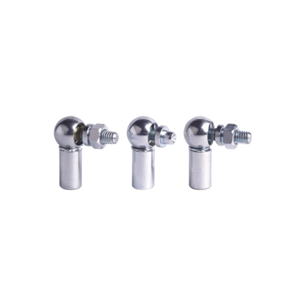
How to select an industrial ball joint
Choose the retention design to suit assembly and maintenance. Establish the load direction and peak force through the linkage travel. Then verify angular movement, surrounding clearance, both threaded interfaces and component materials. Treat catalogue pull and shear values as their stated test or strength figures, not automatically as allowable operating loads.
An industrial ball joint connects a ball stud to a socket so a mechanical linkage can transmit force while changing angle. The useful question is whether that particular assembly can do so throughout your machine's movement, remain securely connected and still be serviced as intended.
This guide covers ball-stud-and-socket connections for mechanical linkages. Automotive suspension joints and pressure-containing pipe ball joints have different design and qualification requirements; the shared name does not make them interchangeable.
1. What is a mechanical ball-and-socket joint?
A mechanical ball-and-socket joint has a spherical ball on a stud, a socket that supports the ball and a construction that retains the two parts. Relative movement at the spherical interface allows the stud and socket to change their angular relationship within the joint's permitted travel.
Ball joint components and how they work
The ball stud connects to one side of the mechanism. The socket body connects to the other. Force passes through their contact interface, while the retention construction prevents separation within its intended operating conditions. A boot or gaiter protects the interface from contamination; it is not the structural retainer.
Ball-stud-and-socket joints versus spherical rod ends
A spherical rod end normally has a bearing eye with a through-bore for a pin or bolt. The connections covered here have a ball stud captured by a socket. Both accommodate angular movement, but they use different mounting interfaces and load paths. Changing from one to the other requires checking the mechanism, not just comparing thread diameters.
For a stud-and-socket assembly, our DIN ball socket and ball stud matching guide goes deeper into selecting the mating components.
2. Choose the type by retention and service access
Industrial ball joints do not have one universal two-type classification. For a linkage buyer, retention construction is a more useful starting point than labels borrowed from automotive suspension.
| Product family | Published construction | What to establish first |
|---|---|---|
| DIN 71802 angle joints | A/B/C without an additional safety clip; AS/BS/CS with a safety clip. | Which complete type and retention arrangement does the assembly require? |
| ES | Three-piece swaged design; permanent stud-and-body assembly. | Can the socket and stud remain together during servicing? |
| FS | Four-piece spring-retained design with a snap ring. | What retention inspection and assembly procedure does the design require? |
| QI | Quick disconnect by retracting a spring-loaded outer housing. | Can the operator reach and retract the housing when installed? |
| QD | Four-piece spring-loaded quick-release design. | Does the complete model meet the release, geometry and load requirements? |
Construction descriptions are from the linked Dongzhou product pages. These families are not a ranking from weakest to strongest.


All four product photographs are from Dongzhou's corresponding official product pages.
Our recommendation: decide whether the connection must come apart
From our manufacturing side at Dongzhou, we recommend settling the service arrangement before matching the thread. If maintenance requires separating the socket from the ball stud, a permanent ES assembly does not satisfy that requirement simply because it fits the rod.
For a quick-disconnect option, include the installed space around the housing in the drawing. A joint that is easy to release on a bench may be inaccessible behind a bracket. We would rather compare the complete installation than treat a matching thread as proof of suitability.
For DIN-style assemblies, specify the full type. Our catalogue distinguishes A/B/C from AS/BS/CS by the additional safety clip and identifies a spanner surface on C/CS studs. Do not omit those features from the purchase description. DIN Media lists DIN 71805 as the standard for angle-joint housings and circlips; a standard identifier still needs the corresponding size and configuration.
3. Read the load path before comparing catalogue values
Identify the force at the ball joint, not only the actuator's nominal force or the load at another part of the mechanism. Record its direction relative to the stud and socket, whether it reverses, and whether starting, stopping or impact creates a higher peak.
Include the supporting bracket and mounting thread in that review. An offset between the joint force and the support creates a moment. Increasing the ball joint size does not automatically resolve an overloaded bracket or an unsuitable mounting arrangement.
Linkage geometry can change the required force
For an ideal planar linkage, neglecting friction and inertia, a force acting at distance r from a pivot produces torque T according to T = rF sin θ. Here, θ is the angle between the radius from the pivot and the force direction. This follows the torque relationship explained by OpenStax.
As a calculation example, assume a mechanism needs 20 N·m at a 50 mm radius. At θ = 90°, the required force is 400 N. At θ = 30°, it is 800 N. The required torque has not changed; the less favorable geometry doubles the force.
This calculation does not select a product or account for shock, fatigue, friction or acceleration. Its purpose is to show why the load review must cover the travel range. A mechanism approaching a straight-line or dead-center arrangement needs particular attention because the useful moment arm decreases.
Same thread, different published pull and shear values
Our QI250 and QD250 share the thread designations below, but their catalogue values differ. ES250 and FS250 also use those thread designations. That makes the four models useful for checking the limits of a thread-only comparison.
| Model | Socket thread | Stud thread | Min. pull test (lb) | Min. shear (lb) |
|---|---|---|---|---|
| ES250 | 1/4-28-2B | 1/4-28-2A | 500 | 500 |
| FS250 | 1/4-28-2B | 1/4-28-2A | 1000 | 700 |
| QI250 | 1/4-28-2B | 1/4-28-2A | 560 | 500 |
| QD250 | 1/4-28-2B | 1/4-28-2A | 950 | 800 |
Source: the linked Dongzhou model tables. Units and column meanings are retained as published. Values apply to the named rows, not every size within each family.
A minimum pull-test value is not a continuous-duty load rating. Establish the test setup, loading direction and acceptance criterion before using it in a design comparison. A working-load decision also requires the operating conditions and an application-specific engineering margin; there is no universal divisor that turns these table entries into safe working loads.
Our recommendation is to compare the complete model, its test basis and its installation. QD250's higher published pull value than QI250 does not establish a longer service life. Likewise, FS250's pull value does not make its retention design a substitute for a required quick-release function.
4. Check movement and clearance through the full travel
The joint's angular movement and the linkage's transmission angle describe different things. Angular movement concerns the stud relative to the socket. Transmission angle concerns the force direction relative to a lever or crank. Passing one check does not establish the other.
Review the start and end positions, then the path between them. Intermediate positions can put the housing, stud shoulder or boot closer to adjacent hardware than either end position. For motion in more than one plane, use the actual three-dimensional assembly.
- Check the stud neck and shoulder against the socket opening throughout movement.
- Include the locknut, mounting bracket, fasteners and any protective gaiter in the envelope.
- Allow space to operate the release housing or access the retention hardware.
- Check tolerances and assembly variation, rather than accepting nominal CAD clearance alone.
We recommend separating two drawing reviews: clearance during operation and access during maintenance. A quick-release joint can move freely yet remain impossible to disconnect without removing another machine part.
For supported lids or covers, the gas spring end-fitting and mounting-bracket guide extends this check to the two mounting points and the surrounding structure.
5. Match both interfaces, not just one thread
Write down the socket connection and stud connection separately. A matching diameter on one side says nothing about the other side's pitch, thread hand, engagement or mounting geometry.
Read a complete thread designation
In the catalogue example, 1/4-28 identifies a nominal quarter-inch diameter with 28 threads per inch. The 2B and 2A designations identify internal and external thread classes respectively. ASME's B1.1-2024 contents distinguish the Class 2A external and Class 2B internal thread tables. Carry the full callout into the drawing rather than shortening it to "quarter-inch thread."
Check thread hand as a separate requirement. Dongzhou lists a left-hand socket-thread alternative for several families; that does not mean every stocked configuration has a left-hand thread. An adjustable linkage also needs a locking arrangement and adequate engagement at its final installed length.
Dimensions that decide whether the assembly fits
Compare ball size and the ball-center location relative to each mounting face. Then check the stud's available threaded length, shoulder position, bracket thickness and nut arrangement. A stud that screws into a bracket may still put the ball center in the wrong location.
The labels used for catalogue dimensions differ between series. Compare the corresponding drawing features, not merely columns with similar letters. For a separately purchased DIN 71805 socket and DIN 71803 stud, establish the mating ball/socket size as well as both external interfaces.
For example, our DIN 71802 table pairs d1 = 8 with an M5 d2 thread in its first size row. Specify the corresponding drawing dimensions and the assembly type, rather than ordering by M5 alone.
6. Specify materials and protection by component
A ball joint is an assembly, so specify its parts individually. "Stainless ball joint" is too broad if the design needs a particular material for the socket, stud, spring and any separate retention hardware.
Our QI and QD pages list Q235A socket material, grade 45 steel studs, grade 20 steel shells and 304 stainless springs in their standard material descriptions. They also list 303, 304 or 316 stainless alternatives for the socket and stud, with passivation. Those alternatives do not establish that every part of the assembly is 316 stainless. See the QI materials list and QD materials list.
For an outdoor or washdown specification, describe the exposure and the consequence of corrosion. Include whether the concern is cosmetic appearance, thread seizure, retention operation or movement at the spherical interface. That gives the material and finish discussion a defined acceptance target.
A protective boot is not a complete environmental specification
The ES and FS descriptions identify neoprene gaiters that help resist dirt contamination. That feature does not establish an ingress-protection rating, chemical compatibility or an operating-temperature limit for the complete assembly. Those properties need their own specifications.
Likewise, a catalogue statement that a joint is filled with lubricant does not establish a lifetime lubrication interval for your machine. Define the movement pattern and environment, then agree the maintenance requirements for the selected construction.
If a coating specification uses salt-spray testing, define the exposure duration and pass/fail criterion rather than asking only for "salt-spray compliant." ASTM's B117 significance and scope notes explain that standalone salt-spray results do not reliably predict performance in natural environments and that the practice does not prescribe a product's exposure period. Test hours should not be converted into a promised number of outdoor service years.
7. Confirm the assembly and send a useful RFQ
Before accepting a model, confirm that the supplied assembly matches the specified retention construction and that its mating interfaces agree with the drawing. After installation, check movement through the required path and verify that retention hardware is correctly fitted using the applicable assembly procedure.
Disconnect a joint only after the machine is in its defined safe maintenance state and the linkage load is removed. A quick-release mechanism is not permission to separate a loaded connection.
What we recommend including in your enquiry
- The current part number, required quantity and a clear photograph if replacing an existing joint.
- An assembly drawing showing both connections, ball-center positions and surrounding hardware.
- Complete socket and stud thread callouts, including thread hand and engagement requirements.
- Peak force, force direction, reversing motion, operating frequency and any impact conditions.
- Required angular movement and clearance through the full linkage travel.
- Exposure, component materials, finish requirements and whether regular disconnection is needed.
We offer customized linkage parts based on drawings or samples. Our recommendation is to send a sample together with a dimensioned drawing where possible: the sample shows the physical construction, while the drawing defines the required interfaces and acceptance criteria. Our drawing-versus-sample RFQ guide explains that distinction in more detail.
Let us compare the complete connection
Send Dongzhou your assembly drawing or existing joint reference, together with the operating load and maintenance requirements. We can compare our DIN-style, ES, FS, QI and QD options, or discuss a non-standard linkage based on your drawing or sample.
Discuss your linkage with Dongzhou8. Industrial ball joint selection FAQs
Can ball joints with the same thread replace each other?
Not on thread size alone. Confirm the retention design, mating ball size, installed geometry, movement and applicable load requirements. Dongzhou's ES250, FS250, QI250 and QD250 share the published thread designations in this guide but have different construction descriptions and catalogue pull or shear values.
Can I use the minimum pull-test value as the working load?
No. A minimum pull-test value is not automatically an allowable operating load. Establish the test basis and consider the actual load direction, duty, movement and failure consequences before selecting an engineering margin.
When should I choose a permanent joint instead of a quick-disconnect joint?
Consider permanent retention when the socket and stud can remain assembled during the intended maintenance procedure. Consider quick disconnect when separation is required, then check release access and the complete model specification. Neither construction is universally the better choice.
Does a stainless socket and stud mean the whole joint is stainless?
No. Specify the shell, spring and separate retention parts as well as the socket and stud. Material alternatives listed for two components do not establish the material of the complete assembly.
Can a ball-stud-and-socket joint replace a spherical rod end?
Only after an engineering review of the mounting interfaces and load path. A spherical rod end normally connects through its bearing bore; a ball-stud-and-socket joint uses a retained stud. Similar angular movement does not make those connections interchangeable.