

Rod Ends: A Depth Guide from Selection to Installation
Rod ends (also known as Heim joints or rose joints) are common mechanical linkage components found in race car suspensions, aircraft control systems, industrial automation, and even agricultural machinery. Their core advantage lies in their spherical plain bearing design, which allows for angular misalignment while carrying loads, combined with a threaded body for length adjustment.
However, this seemingly simple component harbors many pitfalls during selection, installation, and use. Many failures are not due to product defects but rather because the part was used in the wrong application or installed incorrectly. This article explores the engineering practices necessary for the proper selection and use of rod end bearings.
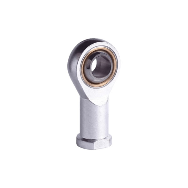
1. Selection: The Foundation of Performance and Longevity
Selecting a rod end bearing is far more complex than simply "picking one by size." You need to comprehensively evaluate load, motion type, environment, maintenance requirements, and more.
1.1 Material and Strength: Trade-offs for Critical Applications
Common rod end materials include mild steel, aluminum alloy, stainless steel, and chromoly steel. Each offers distinct trade-offs in strength, weight, and corrosion resistance.
Chromoly Steel (e.g., 4130): For mission-critical applications such as race car suspensions and aircraft control systems, chromoly steel is typically the first choice. It offers superior strength and fatigue resistance, making it capable of handling high loads and cyclic stresses.Aluminum Alloy (e.g., 7075-T6): Its primary advantage is weight savings. However, its load capacity is comparable to mild steel, and it has poor elongation characteristics. Under high loads, it tends to fracture rather than bend, making it unsuitable for primary load-bearing applications.
Stainless Steel: Offers good corrosion resistance, but strength varies significantly by grade. In corrosive environments where strength is paramount, you may still need to opt for chromoly steel with a protective coating.
Mild Steel: Inexpensive but has limited strength. Not recommended for any structurally significant load-bearing component.
1.2 Lubrication Design: Self-Lubricating vs. Maintenance-Required
The lubrication method directly determines the maintenance cycle and service life of the product.
-
PTFE (Teflon) Lined Type (Self-Lubricating): Features a PTFE fabric liner between the ball and the housing. This is a self-lubricating, maintenance-free design. Key benefits include: no greasing required (which also prevents dirt attraction, extending life), near-zero internal clearance (zero play for higher precision), and consistent breakout torque. Experts from Aurora Bearing note that metal-to-metal rod ends inherently possess clearance that increases with wear, whereas PTFE liners eliminate initial clearance for more consistent long-term performance. In aviation, you must strictly follow the original manufacturer's part number. Substituting alternatives can cause "breakaway torque" to exceed specifications, potentially leading to control system binding and jamming.
-
Metal-to-Metal Type (Requires Lubrication): Steel/steel or steel/bronze friction pairs require regular greasing. They are suitable for applications involving alternating loads, moderate oscillating angles, and moderate sliding speeds.
1.3 Load and Motion Type
Different applications demand entirely different rod end characteristics.
-
High-Speed Rotation + Moderate Load: Prioritize rod ends with ball or roller bearings for smooth rotational motion.
-
Low-Speed, Heavy Load: Plain bearing (sliding) type rod ends are ideal, capable of withstanding high static stresses.
-
Oscillating Motion (Small-Angle Swivel): Both PTFE-lined and metal-to-metal sliding types are suitable. Note that PTFE linings have limited heat dissipation capacity under high-frequency oscillation—consult manufacturer data for specific limits.
2. Installation: Common Mistakes That Can Be Fatal
Proper installation is critical to achieving performance and avoiding premature failure. Incorrect installation forces the rod end to withstand bending moments it was never designed for.
2.1 Avoid Bending Loads
Rod end bearings are engineered to carry pure tension or compression loads. In proper structural design, you must actively avoid subjecting them to bending loads.
Classic Error Case: In a double-wishbone suspension design, connecting the pushrod to a rod end on the lower control arm (LCA). Under braking, the braking torque travels through the lower arm and imposes a massive bending moment on the rod end—this is not its intended load case. The correct practice is to mount the pushrod to the upright/spindle.Bottom Line Principle: While some may oversize rod ends to brute-force withstand bending loads, this violates sound engineering principles. By eliminating bending loads, you can use smaller, lighter rod ends, achieving both performance and weight optimization.
2.2 Minimum Thread Engagement Length
For threaded rod ends (both male and female threads), ensure absolute minimum thread engagement length—failure to do so will lead to thread stripping or fracture at the connection point.
-
Witness Hole Method: Many pushrods feature a witness hole located at a distance of 1 to 1.5 times the thread diameter from the rod end face. For example, with a 1/4-28 thread, the hole sits 1/4 inch from the face. After installation, this hole must be completely covered (the screw-in depth must go beyond this point) for the connection to be considered safe.
-
Practical Check: If visual confirmation is impossible, use a 0.020-inch safety wire to probe the witness hole. If the wire passes through, it indicates inadequate thread engagement—this is absolutely unacceptable.
- 2.3 Locking and Retention
-
Check Nut / Jam Nut: Any rod end adjusted to its final position must be secured with a jam nut and marked with torque stripe paint.
-
Capture Washer: In high-risk applications like aircraft or race cars, consider installing a large-diameter washer (e.g., AN970) on one side of the rod end. If the rod end housing cracks and the bearing escapes, this capture washer can still retain the bearing within its mounting point, maintaining basic control linkage integrity and preventing catastrophic failure.
3. Maintenance and Inspection
Unless a rod end is specifically designed as "maintenance-free," regular inspection is the only way to ensure safety and reliability.
-
Play Inspection: The most intuitive check is feeling for "sloppiness" between the ball and the housing. For race car suspensions, especially front rod ends on four-link or ladder bar setups that endure heavy loads, check regularly for abnormal play or binding.
-
Surface Inspection: For metal-to-metal rod ends, if the ball surface shows discoloration (browning, blackening), roughness, or galling, it indicates micro-welding has occurred—immediate replacement is required.
-
Flexibility Check: Manually articulate the rod end to feel for any "sticking points" or abnormal resistance increase (breakout torque exceeding limits). This is a red-line indicator in aviation applications.
Rod end bearings are the "joints" that connect mechanical structures. Successful application begins with selecting the right material and lubrication type, succeeds through installation designs that avoid bending loads, and is safeguarded by rigorous inspection of thread engagement and internal play. Whether you're building a race car or an industrial machine, respecting these engineering principles will make these small components reliable cornerstones of your design—not hidden sources of failure.