


Direct answer
To manufacture custom linkage components from an engineering drawing, first agree a controlled design that defines the mating interfaces, materials, finished dimensions and operating duty. Review manufacturability before making samples. Use prototypes to answer design questions, inspect production-intent first articles against the released requirements, and approve batch production only after the process and acceptance records are agreed. A sample that fits one machine is not proof of repeatable production.
At Dongzhou, we recommend looking at the complete connection before tightening tolerances on one part. A fork needs its mating eye and pin. A threaded rod end needs a defined adjustment position. A ball joint needs room to articulate and a specified retention arrangement. These relationships determine what the factory must make and what the buyer must approve.
Our customized linkage service covers non-standard connection parts made to customer drawings or samples. Our product range includes clevises, rod ends, ball joints and ball joint assemblies. The approval method below applies to those mechanical connections and their associated pins and mounting parts.
Check whether the requirement really needs a custom part
Begin with the nearest catalog model. A different thread pitch or longer fork may already be a published option. A new pin-center location, unusual mating envelope or changed joint construction may require a separate drawing and review.
For example, Dongzhou's FK clevis table lists FK 8X16 with M8×1.25 and FK 8X16 FG with M8×1. Their nominal thread diameter is the same; their pitches are different. Ordering an "M8 clevis" leaves a functional interface unresolved. Selecting an existing fine-pitch variant is a different purchasing task from designing a new fork.
Write the catalog reference beside the proposed changes, then define the supply boundary. Are you buying a fork alone, a fork with pin and retainer, or an assembled linkage? Dongzhou's FK page offers assemblies with pins, bolts or circlips on request. That does not make every photographed accessory part of every order.
For the detailed input package, use our custom clevis and rod end RFQ guide. The task here is to carry those inputs through the approval decisions, rather than stop at a quotation.
Review the installed interfaces before the outside shape
A manufacturing drawing defines allowable variation. An assembly view explains why that variation matters. Send both when the part operates in a linkage, and identify the drawing revision, units and document precedence. If the PDF and CAD model disagree, resolve the conflict before machining or tooling begins.
ASME's Y14.5 dimensioning and tolerancing standard defines the language for communicating geometric requirements on drawings and models. Specify the applicable drawing system and edition. A supplier should not have to choose the interpretation of a datum or position requirement from context.
| Connection | What the drawing must resolve | What approval should verify |
|---|---|---|
| Clevis, mating eye and pin | Hole/pin fit; fork gap and eye width; hole alignment; usable pin length; retainer interface | Assembly without forced distortion, agreed axial clearance, pin seating and retention |
| Adjustable rod-end linkage | Full threads and hand; pivot-center distance at a stated setting; adjustment range and minimum engagement | Length and locking at the specified setting, plus clearance through the required movement |
| Ball joint assembly | Stud and socket interfaces; mounting geometry; articulation envelope; retention and service access | Correct mounting, unobstructed travel and the agreed retention/function checks |
| Stamped joint bracket | Mounting pattern and seating face; formed geometry; pivot location; free or restrained measurement state | The joint center in the agreed fixture or mounting condition after forming and finishing |
A smaller tolerance is useful only if it controls the failure
A tightly controlled hole diameter will not correct two fork holes that are misaligned. Nor will a precise outside length define the pivot-center distance of a linkage with adjustable threaded ends. Mark the functional features, their relationships and the measurement state before deciding which tolerances need to be tighter.
Our factory-side recommendation is to ask where a failed fit would first appear. Would the pin refuse to enter? Would the eye bind between the fork faces? Would the linkage run out of adjustment? We would use those answers to prioritize the drawing review instead of applying the tightest available tolerance to every dimension.
Keep materials and surface treatments at component level. A stainless fork does not specify its pin, clip or bearing insert. Define the finished fit explicitly, including any coating on mating surfaces. Also describe force direction, peak and repeating loads, movement, exposure and the consequences of failure. A dimensional report cannot validate fatigue life or an application load by itself.
A clevis fit review that exposes two different problems
Consider an illustrative custom clevis assembly. The design team proposes the following finished dimensions: a bore from 10.00 to 10.04 mm, a pin from 9.96 to 9.98 mm, a fork gap from 20.20 to 20.40 mm, and a mating-eye width from 19.90 to 20.10 mm. These are assumed design inputs for the calculation, not Dongzhou catalog tolerances or customer test results.
Check the limits, not just the nominal dimensions
The diametral clearance is the bore diameter minus the pin diameter. Its worst-case limits are:
Minimum: 10.00 − 9.98 = 0.02 mm
Maximum: 10.04 − 9.96 = 0.08 mm
The total axial clearance between the eye and the two inner fork faces is the fork gap minus the eye width:
Minimum: 20.20 − 20.10 = 0.10 mm
Maximum: 20.40 − 19.90 = 0.50 mm
Those are different checks. The first screens the diameter fit; the second screens the width stack. Neither proves acceptable movement, hole alignment, retained-pin geometry or performance under load.
What changes if the dimensions apply before plating?
For a second calculation, suppose both the bore surface and pin surface receive a uniform deposited coating 0.010 mm thick per surface. Assume no masking or post-coating sizing. The bore diameter decreases by 0.020 mm and the pin diameter increases by 0.020 mm, so the diametral clearance decreases by 0.040 mm.
The original 0.02 to 0.08 mm range would become −0.02 to +0.04 mm. Its tightest combination now has interference. The coating thickness here is an assumption, not a recommended specification; actual deposition and final sizes must be established for the selected process.
We recommend resolving the finished-size requirement with the designer, then reviewing masking, machining allowances or post-coating finishing where appropriate. Enlarging the hole without approval could restore assembly while creating excessive play elsewhere. Acceptable clearance depends on the load, lubrication, motion and required positional control.
This example also explains why hand-fitting one prototype is weak approval evidence. A polished pin may enter that sample while the drawing still permits an interference combination in the next batch. The correction belongs in the controlled design and production route.
Agree how the part will reach its finished condition
Design for manufacturability (DFM) means reviewing whether the proposed geometry, material and requirements can be produced and inspected by the intended route. For a linkage, review the sequence as well as the individual operations. A hole inspected before forming may not represent its final alignment; a thread inspected before coating may not represent the delivered thread.
Ask the supplier to identify features that depend on tooling, secondary operations or final assembly. Resolve whether functional bores need sizing after forming or finishing, how threads will be protected or verified, and which surfaces establish the inspection setup. The agreed route must preserve the design requirement, not quietly relax it.
Stamped parts need a formed-part decision
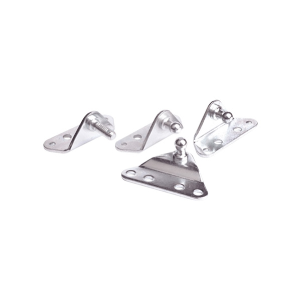
Dongzhou's customized stamping page describes requirement review, die design, tool trials and adjustment before batch production and inspection. That sequence gives a practical reason to assess a formed sample before releasing a bracket design.
A flat blank cannot settle the final pivot position. Define how the bracket seats and whether the acceptance measurement is free or restrained. Our stamped bracket drawing guide examines those measurement states in detail.
For an early prototype made by a different route, record the differences. A machined prototype of a future stamped component may answer an assembly-space question, but it does not demonstrate the formed part's geometry or production repeatability. The same applies when prototype material or surface treatment differs from the released specification.
Separate design learning from production approval
"Sample approved" is too broad unless the approval states what the sample proves. Use named decisions and attach the evidence to each one. The following sequence is a practical approval framework; the purchase agreement should define the exact records and authorization required.
Release the design baseline
Agree the part and assembly drawings, revision, bill of materials, material and finish requirements, and the marked functional characteristics. Close DFM questions in writing. Record whether a requested change is a proposal or an approved requirement.
Use the prototype to answer a specific question
Define the question before making the sample: pin insertion, installation clearance, articulation, adjustment or service access. Record what differs from the intended production part. If a test checks motion without operating load, its approval does not establish loaded performance or fatigue life.
Inspect production-intent first articles
Agree which actual materials, tooling, finishing and assembly steps the first articles represent. Link each measured characteristic to the released drawing and identify the inspected parts. Record actual values and deviations, rather than relying only on an overall pass stamp. Add the agreed functional or performance test records where the requirement calls for them.
Approve the repeat-production controls
Agree inspection points, sampling, lot identification, treatment of nonconforming parts and records supplied with shipments. Where a pilot batch is appropriate, use it to assess the intended production route rather than a separately hand-finished sample. Define who may authorize production and whether any acceptance is conditional.
First article inspection (FAI) records whether identified initial parts meet the applicable requirements. Process capability asks a different question: how a stable process varies relative to its specification limits. NIST's process capability guidance defines capability in terms of a stable process and discusses the statistical assumptions behind capability indices. Do not calculate a process capability index such as Cpk from a few selected prototypes or adopt a universal approval threshold without an agreed method.
Make the acceptance method reproducible
The buyer and supplier must measure the same characteristic in the same defined state. A linkage center distance measured with threaded ends fully seated is a different result from the distance at a specified adjustment setting. A flexible bracket measured free is different from the bracket restrained in a mounting fixture.
For each functional characteristic, agree its drawing reference, permitted limits, inspection stage and setup. Select a suitable gauge or measurement method and define the acceptance decision near a limit. NIST's measurement uncertainty guidance explains why a measured value carries uncertainty; the number of digits on a display does not, by itself, establish the quality of the result.
A fit test and a dimensional check answer different questions
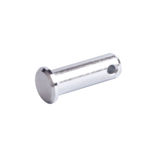
Dongzhou identifies its PC pin range for use with FK and FT clevis joints. For a custom assembly, measure the relevant pin and hole characteristics, then check assembly under the agreed conditions.
A freely inserted pin does not prove every dimensional limit. A diameter reading does not prove that the pin passes through the complete fork-and-eye stack. The checks complement each other.
| Characteristic | Define the check | Record the evidence |
|---|---|---|
| Finished bore and pin fit | Finished state, diameter limits, method and assembly condition | Actual sizes, inspected part IDs and fit-check result |
| Threaded connection | Full callout, applicable gauging requirements and any specified engagement check | Gauge identification/result and separate engagement or assembly evidence |
| Pivot-center distance | Adjustment position, locking condition and measurement references | Measured distance and the setup used |
| Retainer and motion | Selected hardware, seated condition, travel envelope and test conditions | Assembly identity, observations and specified test results |
| Material and finish | Component-specific specification, documentation and any required verification | Material/finish records linked to the inspected lot or parts |
We recommend keeping a reference sample alongside the measured records. A sample helps discuss appearance and assembly feel, but it cannot encode every allowable dimension or prove the grade of an unidentified material. When the sample and drawing disagree, obtain a written decision and update the controlling documents.
Release the batch with a clear change-control boundary
A useful production release identifies the approved part number and revision, the accepted first articles and records, the supplied assembly contents, and any unresolved conditions. It should distinguish full approval from a limited deviation for a named quantity or lot. A temporary concession must not become the next order's unwritten specification.
Retain the connection between shipment and approval: lot identification, the applicable drawing revision, and the material, finish and inspection documents required by the order. Protect finished bores, threads and retained hardware during handling and packing according to the agreed requirements. Packaging is part of the delivery condition, not proof of component performance.
A later change needs an impact review
Changing a thread pitch clearly affects a mating part. Changing a coating, heat treatment, retainer supplier or forming tool may also affect dimensions or behavior without changing the silhouette. Identify the affected characteristics and agree whether new first articles or additional tests are needed before the revised parts enter production.
Our recommendation is to state the reason for every approval return. "Pin binds after finishing" is more useful than "sample rejected." Link the symptom to the requirement, correct the design or process, and repeat the affected checks. If someone must polish, bend or substitute hardware to achieve acceptance, the approved production definition needs to account for that operation.
Start a custom linkage review with Dongzhou
Send the current engineering drawing and an assembly view, with the nearest catalog reference where one exists. Tell us which interfaces are fixed, which features can change, what components the order must include, and what the mechanism must do. If you have a sample, identify whether it is an approved part, a prototype or a field return.
Our customized linkage service is the relevant starting point for non-standard mechanical connections. For formed mounting parts, include the measurement state and refer to our customized stamping service. Define the requested approval evidence with the inquiry so the discussion covers the production requirement as well as the geometry.
Let us review the connection, not just the outline
At Ningbo Dongzhou Transmission, we offer both catalog connection parts and non-standard parts based on drawings or samples. Share your mating pin, eye or threaded interface details with the drawing. We can compare the requirement with our published ranges and discuss the custom geometry, supply boundary and approval requirements with you.
Discuss your custom linkage with DongzhouQuestions before approving custom connection parts
Can a supplier manufacture a custom linkage from a sample alone?
A sample can provide a starting geometry, but repeat manufacture still needs an agreed definition of material, finish, interfaces, allowable variation and acceptance. A worn or repaired sample should not determine new nominal dimensions without a design decision.
Does prototype approval authorize mass production?
Only if the approval explicitly covers the intended production definition and its required evidence. A prototype made with substitute material, a different route or hand-fitting may answer a design question without validating repeat manufacture.
Should all custom linkage orders require a capability study?
No single evidence package suits every order. Agree requirements according to quantity, functional risk and customer obligations. A one-off part and a repeating batch need different evidence; capability analysis also requires suitable process data and statistical assumptions.
What should happen when the approved sample conflicts with the drawing?
Resolve the discrepancy in writing before production. Identify the controlling requirement, revise the affected documents where necessary, and determine which inspections or tests must be repeated. Do not let two incompatible definitions circulate under the same approval.