

Direct answer
Rod end bearing misalignment angle describes relative tilt between the spherical inner ring and its housing under the stated catalog definition. Check that definition and the exact model drawing, then review the installed clevis, spacers, bolt and nearby parts throughout the required motion. Available clearance can be smaller than the catalog angle. An unloaded joint that moves freely has passed a geometry check, not a complete operating-load or service-life assessment.
At Dongzhou, we recommend reviewing the mounted connection before selecting a larger rod end to cure binding. Which surface makes contact first? Is the inner ring seated as the mounting design intends? Does the motion leave the plane shown in the assembly drawing? Those questions are often more useful than comparing bore sizes alone.
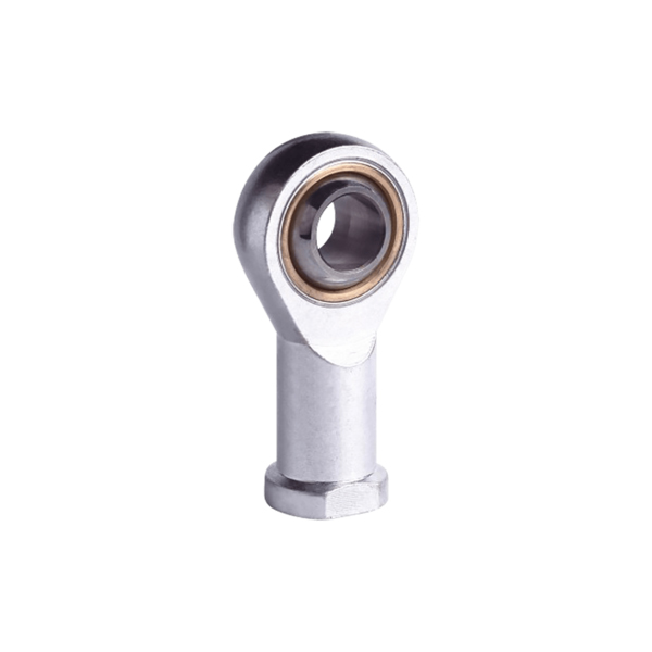
This guide concerns spherical plain rod ends used in mechanical linkages, including our SI-TK female range and POS male range. The check is about the installed joint, not a universal angle for every heim joint or spherical bearing. For the basic construction, see how a rod end bearing works.
What does the catalog misalignment angle mean?
Use the ball-bore axis and the housing's corresponding reference axis to describe tilt. In the centered position, those axes coincide. As the spherical inner ring tilts relative to the housing, they form an angle. In a drawing, identify the two reference directions rather than measuring an arbitrary angle between the shank and a nearby plate.
One-sided tilt, total range and rotation are different
If a specification explicitly permits 12° to either side of its centered reference in one plane, the range from −12° to +12° is 24°. That is a notation example, not a Dongzhou model rating. A bare entry of "12°" does not establish whether it is a one-sided value or a total range without its definition.
Rotation about the ball-bore axis is a different movement from tilting that axis. A linkage can rotate around a pin while needing little relative tilt, or combine pin-axis rotation with a changing out-of-plane angle. An unrestricted pivot in one view does not prove that the spherical joint has enough angular clearance in the other view.
For standardized spherical plain rod ends, ISO 12240-4 covers dimensions, tolerances and radial internal clearances for various dimension series. Its scope does not cover every specialized rod end. A standards reference does not, by itself, approve your spacer geometry, complete assembly or operating duty.
Read a real model row alongside its drawing
Dongzhou's SI-TK web table prints an a ≈ column; the corresponding section drawing labels the angle α°. The POS page also has an a column and an α° drawing. Keep those values tied to their model and drawing instead of replacing them with a generic rod end misalignment angle range.
| Published model | Connection | Published thread | Catalog angle entry |
|---|---|---|---|
| SI 8 T/K | Female, SI-TK | M8×1.25 | a ≈ 14° |
| SI 10 T/K | Female, SI-TK | M10×1.5 | a ≈ 13° |
| POS 8 | Male, POS | M8×1.25 | a = 14° |
| POS 10 | Male, POS | M10×1.5 | a = 13° |
Sources: Dongzhou's SI-TK and POS model tables and their α° drawings. These entries are not installed-clearance measurements or loaded working-angle approvals.
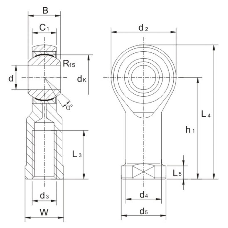
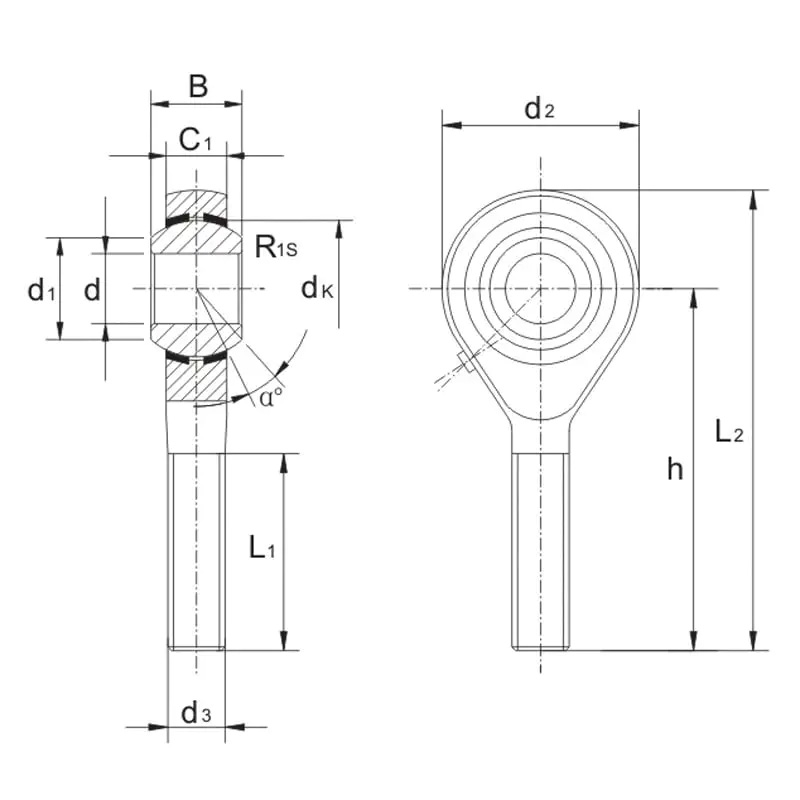
The 8 and 10 model examples have different angle entries. A larger bore therefore does not automatically buy more tilt. Also, equal angle entries do not make a male POS and female SI-TK interchangeable: their connection, housing and maintenance requirements differ.
Find the first contact in the installed hardware
A rod end on a bench has no adjacent clevis plate, bolt head or washer to obstruct it. The installed assembly does. Check the moving housing against every neighboring surface, not just the ball against the race.
For a mounting arrangement designed to clamp the inner ring, the seating hardware must contact the intended inner-ring faces while allowing the housing its specified motion. A washer that overlaps and contacts the housing can change that behavior. Check the actual contact footprint and the approved stack; a nominally correct bolt diameter does not resolve it.
Check rod ends with bushings as a complete stack
Spacer height can move the bracket away from the housing, while spacer outside diameter can still create an early contact. A flanged bushing may also change the effective pin diameter and available grip length. Record the bushing geometry, clevis inside width, bolt head, nut and any retaining hardware together.
Our factory-side view: if a customer sends only a rod end part number, we recommend adding a section through the pin and both mounting faces. That section shows whether a proposed fix creates clearance, transfers clamp force correctly, or merely moves the interference to a different surface.
Check both tilt directions. One side may have a nut, a guard or a larger washer that the other side does not. The spherical joint's own reference geometry may be symmetric while the installed clearance is not.
Check the complete motion, including movement in two planes
Choose a consistent reference for the housing axis and ball-bore axis at each relevant position. A side-view angle alone can miss a second component of tilt. The angles between projected axes are not automatically the complete three-dimensional angle.
For two consistently oriented axis-direction vectors u and v expressed in the same orthonormal coordinate system, calculate their included angle using:
θ = arccos[(u · v) / (|u| |v|)]
This is the vector-angle relationship explained in MIT's dot-product reference. Keep the axis directions consistent so a reversed vector does not turn a small tilt into its supplementary angle. Convert the result to degrees when comparing a degree-based drawing.
Worked geometry example: two views that understate the tilt
Assume the centered housing reference is u = (1, 0, 0). At an intermediate position, the ball-bore direction has an 8° projection in the x-y plane and a 6° projection in the x-z plane, each measured from +x. A direction vector for that particular definition is v = (1, tan 8°, tan 6°).
θ = arctan[√(tan² 8° + tan² 6°)]
θ ≈ 9.95°
The true tilt is neither 8° nor 6°, and adding them to obtain 14° is also incorrect. This expression applies to the projected-angle definition above; it is not a rule for adding arbitrary rotations about different axes.
| Position | x-y projection | x-z projection | Calculated tilt |
|---|---|---|---|
| Start | 6° | 0° | 6° |
| Intermediate position | 8° | 6° | 9.95° |
| End | 6° | 0° | 6° |
Now assume the candidate's specified geometry permits 13° under its stated definition, but the modeled mounting stack first contacts the housing at 12° in the relevant direction. The intermediate position leaves about 2.05° between its calculated tilt and that contact threshold.
These inputs describe a hypothetical drawing review, not an SI-TK or POS installation test. The 2.05° difference is an unloaded geometric result before installation variation or deflection; it is not an approved design allowance. Three sampled positions also do not prove that an unsampled position is clear.
In this review, we would resolve the mounting stack and the complete motion sweep before approving a part change. Checking only the start and end would miss the higher intermediate tilt. A larger bore would not address that omission.
Then review mounting variation, wear and deformation under the relevant duty. These can change both axis orientation and the gap to nearby hardware. Do not simply subtract a universal number of degrees from every catalog value; establish the allowances and validation appropriate to the mechanism.
A practical installed-angle review
Before inspecting or disconnecting a machine linkage, follow its energy-control procedure and secure parts that can move under gravity, spring force or stored pressure. For U.S. workplaces within its scope, OSHA 1910.147 addresses stored-energy control and verification of isolation. Do not force a binding joint through its travel or improvise a powered test to find a contact point.
- Identify the exact rod end, its drawing and the complete mounting stack. Include spacers, washers, pin or bolt, nut, clevis and adjacent covers.
- Define the housing reference, the ball-bore direction and the required positions. A protractor reading from the shank alone is incomplete unless its relationship to those references is established.
- Review the continuous CAD motion or enough justified positions to capture changes in direction and clearance. Include intermediate positions and both sides of the tilt envelope.
- Compare the model with a safely unloaded assembly in the approved mounting condition. Check whether seating, interference or distortion changes after the specified fastening procedure.
- Record the smallest relevant gaps, first-contact locations and unresolved load cases. Agree the additional engineering verification before operating an altered assembly.
We recommend recording the point of contact as carefully as the angle. "Housing touches the right spacer at this stroke position" directs a design review. "The bearing will not swivel enough" could refer to the race, spacer, bolt head, mounting plate or surrounding machine.
| Check | Useful evidence | What it does not establish alone |
|---|---|---|
| Catalog and model drawing | Exact angular callout, convention and part geometry | Clearance to user-supplied hardware |
| CAD motion sweep | Axis directions, intended travel and modeled interference | Unmodeled tolerances, actual seating or real deformation |
| Unloaded assembled check | Contact and freedom of motion in the stated fastening condition | Working-load suitability, wear or fatigue life |
| Application-specific validation | Results under agreed load, motion and acceptance conditions | Unexamined operating conditions or another hardware stack |
A tilt calculation is not automatically a force-angle calculation. The direction of the applied force must be defined separately. Likewise, a low percentage of catalog angle and a low percentage of a load figure do not combine into an approval of the complete linkage.
Spacers and mounting changes: what must be rechecked?
Fix the identified restriction. If the bracket is the first contact, changing the bearing bore may do nothing. If the required motion exceeds the selected joint's own definition, adding external space does not make its bearing interface suitable for that duty.
| Proposed change | Potential purpose | Recheck before approval |
|---|---|---|
| Change the mounting reference or orientation | Redistribute required tilt around the centered position | Full motion, force direction, locking and surrounding clearances |
| Increase clevis inside space | Move plates away from the housing | Pin support span, bracket behavior and the complete spacer stack |
| Use compatible spacers or flanged bushings | Provide intended inner-ring seating and local housing clearance | Seating diameter, flange geometry, grip length and fastening condition |
| Review a high-misalignment rod end or engineered bushing system | Use geometry designed for the additional motion | Exact assembly limits, bearing support, effective bore/pin size and load requirements |
High-misalignment spacers are not a universal accessory. If a bushing occupies part of the existing bore, the mating pin diameter or the bearing size may need to change. Any resulting pin-strength and bending assessment belongs in the revised design. A narrower contact face also needs an appropriate seating and support review.
Our recommendation is to compare the revised assembly, not the spacer in isolation. Avoid grinding a housing lip, substituting an arbitrary washer or loosening the mounting fastener to gain travel. Such changes can affect retention or fastening as well as clearance.

Keep the construction decision separate
Dongzhou describes SI-TK as a maintenance-free female range with PTFE lining, and POS as a maintenance-required male range with a lubrication provision. Select the required construction and connection as well as the angle.
For custom rod ends or mounting geometry outside the published arrangement, our customized linkage service accepts drawing- or sample-based requirements. Include the mating hardware and required motion so the discussion is about the connection the machine uses.
Binding clues and the next check
A symptom can guide inspection without proving the cause. Start with the mounting evidence before assigning every tight joint to bearing damage.
- If movement becomes restricted only after fastening, check the approved stack, seating footprint, alignment and distortion.
- If resistance appears at a repeatable stroke position, inspect the corresponding housing, spacer and bracket clearance in both planes.
- If a polished contact mark appears on a housing edge or spacer, match its location to the modeled motion and check for unmodeled hardware.
- If there is no external contact but motion remains rough, inspect contamination, corrosion, the bearing interface and the applicable maintenance requirements.
Do not treat normal breakaway resistance and a hard geometric stop as the same observation. Record whether the resistance is continuous, localized to a position, or changed by assembly. If a shank, mounting plate or fastener has deformed, stop treating it as a simple clearance adjustment and arrange an engineering review.
Send Dongzhou the joint in its installed position
Send the complete SI-TK, POS or other rod end designation, its mounting section, the required movement and the load conditions. Add the clevis inside width, spacer or bushing geometry, mating bolt or pin, fastening requirements and photos of the surrounding space. Identify the reference axes and whether supplied angles are one-sided, total range or projected angles.
For non-standard hardware, our drawing-and-sample RFQ guide explains how to define the interfaces. A sample is useful, but the controlled drawing and agreed motion requirement should resolve what the next parts must reproduce.
Let Dongzhou review the part and the mounting stack together
Share your model reference and an assembly view with Ningbo Dongzhou Transmission. We can compare the requirement with our published rod end ranges or discuss a non-standard connection based on your drawing or sample. Showing the spacers, pin and travel gives the review a clearer starting point than a bore size alone.
Discuss your installed rod end with DongzhouQuestions before changing the joint
Does a 14° catalog entry mean the joint can move ±14° in my machine?
Read the entry using that model's diagram and angular convention. Then check the installed hardware, required motion and operating conditions. A catalog value alone does not establish the machine's available clearance or loaded working angle.
Can adding washers increase rod end misalignment?
A compatible spacer can create clearance in a suitable mounting design, but an ordinary washer may overlap the housing or change the seating. Specify the geometry and recheck the complete stack, fastening, pin support and motion.
What angle allowance should I leave?
Establish it from the mechanism's installation variation, actual motion, deformation, wear and consequences of contact. There is no single allowance in degrees that can approve every rod end assembly. Keep geometric clearance and operating-load verification as separate checks.