

A replacement clevis can have the right bore and still put the pin in the wrong place. Before ordering, compare the complete threaded connection, the fork interfaces and the installed position against the same references.
Can a DIN 71752 or ISO 8140 clevis replace another one? A shared standard reference helps identify a candidate; it does not settle every replacement condition. Match the selected variant, drawing revision, dimensions and tolerances, thread pitch and hand, pin retention, and required movement. Then review material and application suitability separately.
1. Clevis rod end, clevis joint or yoke end: identify the part first
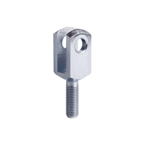
A clevis rod end is the fork-shaped component at a rod connection. A clevis joint also involves its mating part and pin; the retention arrangement keeps that pin in position. Buyers may use names such as rod end clevis, clevis fork or yoke rod end for related components. The name alone does not identify the supplied assembly.
Start by marking what the order includes: the fork only, a fork with pin and retainer, or a larger adjustable linkage. This prevents a catalogue photograph of a complete clevis assembly from becoming an assumption about the quotation.

What the standard reference tells you
DIN Media lists DIN 71752:1994-04 under fork joints and yokes. ISO 8140:2018 addresses mounting dimensions for pneumatic-cylinder rod-end clevis interchangeability. Record the edition required by the drawing or purchase specification rather than treating every abbreviated catalogue label as the same document.
These references answer a different question from a supplier's series code. The standard identifies the relevant specification; the series and complete part number identify the proposed product. The controlled drawing establishes the requirements to compare, and the application review establishes whether the assembled connection suits its duty.
For initial selection of the whole fork, eye and pin arrangement, use our pneumatic cylinder clevis and pin selection guide. The checks below focus on comparing an existing connection with a replacement.
2. Decode the part code without guessing the thread
Read a supplier's code beside that supplier's table. Do not turn one size number into a universal thread designation or carry a suffix meaning across brands.
Dongzhou's FK table separates the bore field d1 from the thread field d2 and distinguishes regular and fine-thread options. Keep the complete variant on the enquiry, drawing comparison and order. For an adjustable threaded clevis, also confirm the specified thread hand and locking arrangement.
Why I separate a 25 mm bore from an M24 connection
I use the FK25X50 entries in Dongzhou's clevis catalogue to check two assumptions that can mislead a replacement comparison. The regular FK25X50 lists a 25 mm bore and an M24 × 3 thread. FK25X50 FG also lists a 25 mm bore, but its thread is M24 × 2.
The first result is that the 25 in this model code must not be read as an M25 thread. The second is that a matching bore and M24 nominal diameter still leave a 1 mm difference in specified thread pitch between these variants.
For a replacement review, I would enter the bore and complete thread designation in separate rows. I would then match the proposed variant to the rod's specified thread before reviewing the remaining geometry, engagement and locking requirements. Neither an identical nominal bore nor a shared standard reference settles that thread comparison.
This gives me a specific purchasing instruction: retain the full variant and thread callout in the order. The catalogue establishes the difference between these two options; acceptance of a supplied part still depends on its drawing and actual inspection evidence.
For another supplier's clevis rod ends catalog, repeat this check from its own designation rules. A suffix that changes pitch in one series may mean something else in another. A cross-reference is a starting point for checking the interfaces, not a reason to discard the original callout.
3. How to read a clevis rod end catalog and dimension drawing
Compare physical features first and letter symbols second. A symbol is useful only after you know its endpoints, direction and reference. Two fields both called “length” can describe different parts of the connection.
Separate the opening, depth and axial position
The fork opening must be compared with the mating eye's width and the specified fit. Slot depth concerns how far the eye and surrounding geometry can enter the fork. The distance from an installation reference to the pin axis determines where the joint sits. None of these checks replaces the others.
For an adjustable connection, write down the position being compared. Is the dimension taken from the clevis body face, a rod shoulder, a locknut face or another assembly datum? Is the thread engagement fixed? Does the stated centre-to-centre distance belong to the complete linkage rather than the clevis alone? Keep those conditions with the number.
| Physical requirement | Record from each drawing | Do not substitute |
|---|---|---|
| Pin interface | Bore size and limits, axis position and associated geometric requirements | A nominal pin diameter without its fit requirements |
| Fork interface | Opening, slot depth, arm geometry and mating-eye requirements | Outside fork width for the clear opening |
| Rod connection | Internal or external thread, full designation, usable engagement and locking condition | Nominal thread diameter alone |
| Installed position | Pin-axis distance from the agreed mounting reference at the defined adjustment | Overall part length |
| Space and movement | Body envelope, neighbouring parts, travel and pin/retainer access | A static catalogue outline alone |
Keep tolerances and notes attached to the value
A useful comparison row contains the nominal value, limits or tolerance callout, units, datum and applicable note. Keep the original symbol beside the physical feature name so another reviewer can trace the comparison back to the source.
For CAD, confirm the selected configuration and units before measuring. Check which tolerances, material requirements and notes accompany that model. A model that fits in an assembly is useful geometry evidence, but it does not by itself establish every requirement for a supplied part.
4. Compare short and long versions before checking the envelope
Matching the bore and thread can leave a substantial difference elsewhere in the clevis. The following entries from the Dongzhou FK catalogue show why the remaining fields must stay in the comparison.
| Model | d1 (mm) | Thread d2 | g (mm) | l1 (mm) | l2 (mm) |
|---|---|---|---|---|---|
| FK8X16 | 8 | M8 × 1.25 | 16 | 42 | 32 |
| FK8X32 | 8 | M8 × 1.25 | 32 | 58 | 48 |
The g, l1 and l2 labels retain the source catalogue's notation. Use that catalogue's applicable drawing to identify their physical endpoints; do not transfer the letters directly to another supplier's drawing.
The rows establish that an 8 mm bore and M8 × 1.25 thread do not uniquely identify the geometry. They do not establish that changing the thread adjustment will recover the original pin position. Review engagement, locking and the installed reference before making that proposal.
Check the moving envelope as well as the static outline. Follow the mechanism through its required travel and review clearance at the fork body, mating eye and retainer. Also check whether the pin can be inserted and removed in the installed location. A part that clears after assembly can still leave no practical access for maintenance.
5. Confirm fit and finished condition, not just nominal dimensions
“The pin goes through” is a limited observation. It does not establish the bore's full dimensional conformity, the eye-to-fork relationship or the joint's required movement.
Compare the pin and bore requirements together, then compare the fork opening with the mating eye. If a tolerance class appears on the drawing, use the applicable tolerance specification and nominal-size range to establish its limits. Do not invent a clearance target from a catalogue photograph or from another size.
Compare parts in the same supply condition
State whether the dimensions apply before or after the specified finish. A dimension measured on an unfinished sample is not automatically evidence for the finished supplied part. The inspection plan should identify the required condition and the features that need verification in that condition.
For material and finish choices, our clevis materials and finishes guide covers that separate decision. Do not use a common coating name as evidence that two suppliers apply the same process or provide the same dimensional result.
If the code, dimension table and drawing disagree, stop the automatic match. Ask for the drawing and revision that will govern the order, then resolve the inconsistent field in writing. Choosing the convenient value leaves the receiving inspector with an unresolved acceptance criterion.
6. Threaded clevises and clevis assemblies: compare connection and function
A replacement can resemble the original fork while changing how the rod connects or how the assembly moves. Treat connection type and intended freedom of movement as separate comparison rows.
| Candidate | Published distinction | Question to resolve |
|---|---|---|
| FK clevis | Female threaded rod connection; selected thread options in the FK table | Does the complete thread and required engagement match the rod? |
| FT male-thread clevis | External threaded shank | Does the mating component accept that connection without changing the installation? |
| FKR rotating-shaft clevis | Rotating-shaft function | Is that rotation required and compatible with the mechanism's restraints? |
Rotation and anti-rotation are different requirements
Do not treat a rotating-shaft version as a fixed clevis with a different name. Review the intended movement, its axis and the application's restraints. Likewise, an anti-rotation requirement needs a defined means of restraint; a shared standard reference does not specify the entire installed locking arrangement.
Keep the pin, retainer and mating eye in the review. A different retainer can change the required hole or groove, access space and assembly method. Carrying the old pin arrangement forward without checking it can leave an otherwise careful drawing comparison incomplete.
Clevis-to-clevis layouts and turnbuckle connections
A “clevis to clevis” description may refer to a larger linkage layout. It is not an instruction to mate two fork openings directly. Establish the actual mating components and pins from the assembly drawing.
For a turnbuckle clevis end, confirm the complete adjustment system, including the specified left- and right-hand threads where used, engagement and locking. Those requirements belong to the assembly; a catalogue listing for an individual threaded clevis does not establish a rated turnbuckle assembly.
7. Dimensional interchangeability is not a load rating
A geometric match establishes neither equal strength nor equal service life. Keep material, treatment and application requirements in the replacement review even when the candidate fits the existing interfaces.
The ISO 8140:2018 abstract identifies a 1,000 kPa (10 bar) pneumatic-cylinder series context. That pressure reference is not a universal working-load rating for every fork carrying the standard number. A buyer seeking a hydraulic cylinder clevis should therefore provide the actual cylinder and connection requirements, rather than infer suitability from a pneumatic mounting-standard label.
The responsible designer needs the applicable loading and movement conditions, including relevant side loads, shock or repeated loading, together with the material and component requirements. Do not compare a static catalogue value with a working requirement unless its meaning and conditions are compatible. If this evidence changes, treat it as a new approval question even when the dimensions remain unchanged.
8. A drawing-to-drawing replacement checklist
Use the following process to prepare a traceable clevis replacement comparison. Its output is a documented candidate review for the responsible approver, not an automatic declaration of interchangeability.
How to prepare a clevis replacement comparison
-
Identify both parts and their governing documents
Record the existing and proposed supplier, complete variant, drawing revision, specified standard edition and supply scope. Include the mating eye, pin, retainer and locking parts in the assembly record.
-
Match physical features and references
Mark the bore and pin axis, fork opening, rod connection and installation datum on both drawings. Retain each original symbol beside its physical description, and put values into the same units.
-
Compare limits, configuration and function
Compare the complete thread, engagement, dimensional limits, finished condition and installed pin position. Review the required movement, clearance and retention access at the defined adjustment and locking condition.
-
Resolve differences and missing evidence
Assign each item a status: matched, different or not established. Refer conflicting or missing requirements to the responsible reviewer and obtain the governing drawing or specification before closing them.
-
Define sample checks and release criteria
Agree which dimensions, thread requirements and assembled fit or movement checks will confirm the candidate. Record the results against the agreed criteria, and obtain the required material and application approval before release.
| Item | Original requirement | Candidate requirement | Evidence and decision |
|---|---|---|---|
| Bore and fork interface | Size, limits, opening and references | Corresponding physical features and limits | Drawing/revision; match or recorded difference |
| Thread and installed position | Full designation, engagement and adjustment condition | Same fields from the selected variant | Drawing plus defined assembly checks |
| Movement and retention | Required freedoms, restraints and pin arrangement | Proposed function and included parts | Assembly review; differences resolved |
| Material and duty | Specified supply condition and application requirements | Proposed specification and supporting records | Responsible review and release decision |
How I approach a clevis replacement review
For a clevis replacement, I start with the connection drawing rather than the standard number in the product title. I want to identify the existing part, the mating components and the position that the replacement must preserve. A matching bore or nominal thread is only one part of that review.
The difficulty comes when two catalogues use different symbols, or when a dimension has no clear reference. I would first mark the pin axis, the threaded connection and the fork opening on each drawing. Then I would compare the same physical features, keeping the original symbols beside them for traceability.
I separate overall length from the pin's installed position. If the connection is adjustable, the comparison needs a defined adjustment and locking condition. Without that condition, two reviewers can compare different assemblies while believing they are checking the same dimension.
For the threaded connection, I need the full designation, including pitch and hand where specified. I also check whether the candidate has an internal or external thread. Similar fork geometry cannot resolve a mismatch at the rod connection.
The pin and retainer remain part of the decision. I would check their working positions and available assembly space against the mating eye and fork. If the replacement changes the retention arrangement, I would review that change explicitly rather than carry the old approval across.
My final comparison separates confirmed matches from differences and missing information. When a catalogue entry is unclear, I ask for the applicable drawing instead of choosing the interpretation that makes the parts appear interchangeable. I would then use the agreed sample checks to confirm the required fit and movement. Geometry, material and application suitability need their own evidence before release. I keep the unresolved items visible so that a purchasing decision cannot silently become an engineering approval.
If no standard candidate meets the required interfaces, discuss a custom clevis against the unresolved requirements. Send the comparison and applicable drawings with the enquiry. Our drawing-and-sample RFQ guide explains the inputs needed for that discussion.
9. Questions about DIN 71752 and ISO 8140 clevis replacement
Are all clevises labelled DIN 71752 or ISO 8140 interchangeable?
No. Compare the applicable standard edition, selected variant and governing drawing, then check the interfaces, tolerances, assembly function, material and duty. A shared catalogue reference does not resolve every replacement requirement.
Does a 25 mm clevis bore mean the thread is M25?
No. Bore size and thread designation are separate fields. Dongzhou's FK25X50 catalogue entry pairs a 25 mm bore with M24 × 3; the FK25X50 FG option uses M24 × 2. Keep the full selected designation on the order.
Can I replace a short clevis with a long one if the thread matches?
Only after checking the installed pin-axis position, available engagement, locking condition and movement envelope. A matching thread does not show that adjustment will preserve the original geometry or assembly requirements.
Is a matching CAD model enough to approve the replacement?
No. Confirm the model's configuration and units, and review its associated tolerances and notes. Geometry fit alone does not establish the supplied part's material, finished condition, retention arrangement or suitability for the application.
Can I reuse the existing clevis pin and clip?
Do not assume so. Check the proposed clevis, mating eye, pin working position and retention features together. Review the existing parts' condition and the applicable reuse requirements before accepting them in the replacement assembly.
Is a rotating-shaft clevis a direct substitute for a fixed clevis?
Not on dimensions alone. Check whether the added rotation is required, what axis it acts around and how the mechanism restrains movement. Confirm the complete connection and application requirements before accepting the change.
Keep the full variant, drawing revision and unresolved differences together through purchasing and inspection. The replacement decision should remain traceable to the connection that has to work, not just the standard number printed above a catalogue table.